PS2 Linux Programming
Using the DMAC
Introduction
This tutorial will provide commentary on the
associated code that is used to draw 4 Gourard shaded triangle primitives using
the PS2 Linux Development Kit and the SPS2 direct access module. The Direct Memory
Access Controller (DMAC) will be used to transfer data to the graphics
processor. Some prerequisite knowledge fundamental to the understanding of the
program will be provided.
The Direct Memory Access Controller (DMAC)
Figure 1 shows the main
internal data paths that exist within the PS2. The DMAC will be discussed here
since it is vital to maximising the performance of the PS2. The DMAC is used to
handle data transfers between main memory and each of the processors. It can
also be used to transfer data between main memory and the scratchpad memory
(SP) of the EE Core.
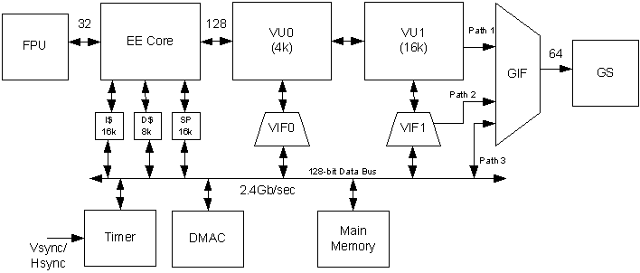
Figure 1
In terms of performance,
the DMAC bus can transfer data at a maximum rate of 2.4Gb/sec. This can be
compared with the AGPx4 bus that has a bus bandwidth of 1.1Gb/sec and the AGPx8
bus that is 2.1Gb/sec.
Due to the design of the
PS2, it is only possible to transfer data using the DMAC if the physical
address of the memory to be transferred is know. Normal program variables and
dynamically allocated memory (in an operating system such as Linux) use virtual
addresses which are constant for a given program, but the physical address of
these variables and memory may change as the operating system pages them in,
out, and around physical memory. This leads to one of the main purposes of the
SPS2 module, which is the allocation of un-swappable physical memory that is
guaranteed to have a constant physical address. In essence this allows the
programmer to used the power and performance of the DMAC whilst developing
applications under PS2 Linux.
Un-swappable memory is
allocated using the sps2Allocate() function. This function takes 3 parameters,
the first being the amount of memory to be allocated in bytes. It is
recommended that this value be a multiple of 4096 but any value supplied will
be rounded up to the next highest 4096 boundary. The second parameter is a set
of behaviour flags. SPS2_MAP_BLOCK_4K must always be used since it is the only
block size currently supported. Optionally this flag may be bitwise ORed with
SPS2_MAP_UNCACHED or SPS2_MAP_CACHED. If neither of these flags is used, the
memory will be cached by default. Cached memory can be faster than un-cached
memory, but requires the use of the sps2FlushCache() function before the DMAC
Transfer is started so that any data that has been modified in the cache is
written back to memory. The final parameter is the device descriptor that was
received from sps2Init().
sps2Allocate() returns
either a pointer to an sps2Memory_t structure or null if there is not enough
memory in the system for the request. The sps2Memory_t structure contains
information about the position and organisation of the allocated memory but the
only field that is of concern is pvStart. This, as the name suggests, is a
pointer to the start of the allocated memory, and is a virtual address that can
be used in the same manner as a normal pointer. pvStart is of type void and
should be cast to a pointer of a suitable type before use. Once the allocated
memory is no longer required, it should be release back to the operating system
by passing the sps2Memory_t structure to the sps2Free() function.
Data to be shifted by the
DMAC needs to be properly aligned in memory – the start address of the data
must be aligned on a 16-byte (qword) boundary. Thus, the starting address of
any memory to be transferred must always meet the condition ((Address &
0xF) == 0). Also, the data is transferred in chunks of 1 qword, so the minimum
amount of data that can be transferred is 16-bytes. Note that sps2Allocate()
will return a pointer which is properly aligned.
There are 4 different
modes of DMAC transfer: Normal, source chain, destination chain, and
interleave. In this tutorial only normal mode transfers will be considered. The
DMAC transfer process is controlled by a number of 32-bit registers within the
EE core. Some of these registers have multiple values packed together into
their bits. The channel control register (CHCR), the memory address register
(MADR), and the quad word count register (QWC) are all needed to set up a
normal mode DMAC transfer. SPS2 has unions and structures to access these
registers and they are listed below for clarity. The relevant parts of these
unions will be described as required.
typedef union Dn_CHCR {
sps2uint32
i32;
struct {
unsigned
int DIR :1;
unsigned
int _PAD1 :1;
unsigned
int MOD :2;
unsigned
int ASP :2;
unsigned
int TTE :1;
unsigned
int TIE :1;
unsigned
int STR :1;
unsigned
int _PAD2 :10;
unsigned
int TAG_PCE :2;
unsigned
int TAG_ID :3;
unsigned
int TAG_IRQ :1;
} s;
} Dn_CHCR_t;
typedef union Dn_MADR {
sps2uint32
i32;
struct {
unsigned
int ADDR :31;
unsigned
int SPR :1;
} s;
} Dn_MADR_t;
typedef union Dn_QWC {
sps2uint32
i32;
struct {
unsigned
int QWC :16;
unsigned
int _PAD1 :16;
} s;
} Dn_QWC_t;
The
DMAC has ten separate channels for transferring data between the various
processors and memory within the PS2. Transfer to the Graphics Interface (GIF)
has a channel ID number of 2 and the register names used for this channel are
in the form EE_D2_XXXX where EE represents an EE core register; D2 refers to
the channel ID number and XXXX is the relevant control register to be accessed.
Page 42 of the EE users manual has a complete listing of all the DMAC channels
in the PS2.
Normal mode transfer to
the GIF moves a continuous section of data from main memory to the GIF over
channel 2. All that is required for the transfer is to set up 3 registers:
EE_D2_QWC, EE_D2_MADR and EE_D2_CHCR.
The first register QWC (EE
Users Manual page 79) is the number of qwords to be transferred.
The second register MADR
(EE Users Manual page 75) is the start address in memory of the data to be
transferred. This address must be the physical address of the memory where the
data resides. To get this physical address a pointer to the start of the memory
(a virtual memory address pointer) along with a pointer to the sps2Memory_t
structure is passed to the sps2GetPhysicalAddress() function which will return
the physical address of the memory. The ADDR field of the MADR register is then
set to this physical address. The SPR field of the register should remain at
zero.
The Final register is the
channel control register, CHCR, (EE Users Manual page 74). This register has a
number of fields; but only two of them, MOD and STR are of interest at this
time. The MOD field tells the DMAC what mode of transfer is required. In this
case MOD is set to CHCR_MOD_NORMAL, which is normal mode transfer. Setting the
STR bit of CHCR to one will start the DMAC transfer. The instant this data is
written into the CHCR register the DMA transfer over channel 2 is started and
the specified data is transferred to the GIF.
It is necessary to wait
for the DMAC transfer to complete before any more processing is done, and this
is achieved by calling the function sps2WaitForDMA(2, iSPS2Descriptor) . This
function will not return until the STR bit of EE_D2_CHCR has been set back to 0
by the DMAC.
While normal mode
transfers are nice and simple, they are not as powerful as some of the other
methods such as source chain mode transfers. Also, SPS2 introduces an added
complication in that the memory it allocates is only physically contiguous in
4k chunks. This means that it is only possible to send up to 4kBytes of data at
a time using normal mode transfer. It is possible to circumvent this limitation
using the other modes of transfer that the DMAC has available, but these
techniques are beyond the scope of the present tutorial and will be described
later.
The Program Code
Now that the DMAC process
has been discussed it is possible to understand the example code provided.
A 12 x 3 array
(VertexData) holds the vertex data of four triangles that are to be drawn on
screen, and a similarly sized array (VertexColors) holds the colour for each
vertex. Note that the number of vertices to be drawn is calculated and stored
in the iVertexCount variable that will be used to configure the primitive data.
iColourCount is also calculated and an assertion is made that these two
variables contain the same value. SPS2Desciptor, which is the handle to be used
for SPS2 and pMemory, which is a pointer to the memory structure used for
allocation are declared.
Moving to the main()
function the following variables are declared: iQWC which will contain the number
of qwords of data to be transferred; and chcr which is used to control the DMAC
transfer process. The MOD field of chcr is set to CHCR_MOD_NORMAL and the STR
bit is set to 1. Remember that the DMAC transfer will not commence until this
value is written into the CHCR register.
After the SPS2 module is
initialised, 4096 bytes of memory are allocated in un-swappable space using
sps2Allocate(). This memory will be used to store the graphics packet which
will be DMAC transferred to the GIF. Note that the memory is uncached at this
time for simplicity. Finally, before the main render loop is entered, the
screen is initialised with sps2UscreenInit().
Before the render loop is
discussed it is best to review the BuildGSPacket() function.
Building the Primitive
Data
The BuildGSPacket()
function takes a pointer to the start of the allocated memory which is cast to
sps2GIFTag_t. A pointer to packed register data (sps2GIFPackedRegister_t) pREG
is also declared for use in this function. As in tutorial 1 the GIFTag is
configured along with the primitive data and the complete packet is stored in
the allocated memory. A few points to note about this function:
1. The graphics packed consists of one GIFTag
followed by primitive data.
2. The primitive data consists of 24 qwords,
each vertex is described by two registers (RGBAQ and XYZ2) and there are 12
vertices. By the end of this function, NLOOP = 12 and NREG = 2 in the GIFTag.
3. The
number of qwords written to memory is returned by this function.
The Render Loop
At the start of the render
loop the buffer to be drawn into is cleared to a light blue colour. The
graphics packet is then constructed in allocated memory, the qword count being
returned by the BuildGSPacket() function. The EE_D2_QWC register is set to the
number of qword to be transferred. The memory address pointer which points to
the start of the memory to be transferred is set into the EE_D2_MADR register.
Note that this is a physical address which is obtained from the
sps2GetPhysicalAddress() function. The DMA transfer is started by writing to
the channel control register with the previously configured data. The render
loop then waits for the DMAC process to complete, then swaps the display and
draw buffers once the monitor has completed scanning out the previous frame.
Conclusions
This tutorial has reviewed
the process necessary to access and use the DMAC within the PS2. Great care
must be taken when accessing the DMA controller directly and it is important to
check that code is correct before being executed. Even the slightest mistake
can cause the PS2 to crash and a complete reboot will probably be required. In
order to get the best performance out of the PS2, low level programming such as
that described in this tutorial is required, but accessing this power does
require the programmer to be vigilant. Judicious use of the assert() function
(as illustrated in the code) can help identify and prevent undesirable crash
events.
Dr Henry S Fortuna
University of Abertay
Dundee