PS2 Linux Programming
Creating a Point Light Source
Introduction
In this tutorial the use of a point light source will be illustrated. The lighting calculations necessary for the point light source will be computed using vector unit 1.
Background
Point lights have colour and position within a scene, but no single direction. They give off light equally in all directions, as shown in the following illustration.
A light bulb is a good example of a point light. Point lights are affected by attenuation and range, and illuminate a mesh on a vertex-by-vertex basis. During lighting calculations, the point light's position in world space and the coordinates of the vertex being lit are used to derive a vector for the direction of the light, and the distance that the light has to travel. These parameters are used, along with the vertex normal, to calculate the contribution of the light to the illumination of the surface. It should be noted that in the example code provided, the distance from the light source to the vertex being lit is not taken into account – it is left as an exercise for the reader to include this distance into the calculations performed by VU1.
The above diagram illustrates the calculations that must be performed when using a point light source. The vector L is derived from the position of the light source and the vertex being lit. The light intensity at the vertex due to the point light source is then derived from the dot product between the light vector and the vertex normal.
Light Intensity a L.N
A small angle will give high intensity whilst a large angle will give low intensity. Note that the position of the viewer (camera) does not affect the calculations in any way.
Example Code
In order to perform the lighting calculations the position and colour of the point light source must be passed to VU1 along with the other required data discussed in previous tutorials. The format of the static part of the packet sent to the VU is illustrated below.
|
Address |
Data |
|
0 |
Scaling Vector |
|
1 |
Point Light Colour |
|
2 |
Point Light Position |
|
3 |
Unused |
|
4 |
Unused |
|
5 |
Unused |
|
6 |
Unused |
|
7 |
Unused |
|
8 |
Transformation Matrix Row #0 |
|
9 |
Transformation Matrix Row #1 |
|
10 |
Transformation Matrix Row #2 |
|
11 |
Transformation Matrix Row #3 |
|
12 |
World Matrix Row #0 |
|
13 |
World Matrix Row #1 |
|
14 |
World Matrix Row #2 |
|
15 |
World Matrix Row #3 |
VU1 Data Memory Layout
The point light source calculation are performed with the following VU code.
lq Norm, NormStart(Counter) ; Load the normal
MatrixMultiplyVertex Norm, fLightTrans, Norm ; Transform normal into world space
MatrixMultiplyVertex Vert, fLightTrans, fVert ; Transform vertex into world space
sub.xyz ToLight, LightPos, Vert ; Get vector from the vertex to light
VectorNormalizeXYZ ToLight, ToLight ; Normalise this vector
VectorDotProduct fIntensity, ToLight, Norm ; Get the intensity
max.x fIntensity, fIntensity, vf00 ; Clamp to > 0
mini.x fIntensity, fIntensity, vf00[w] ; Clamp to < 1
lq fLightCol, LightCol(vi00) ; Load the light colour
mul.xyz fLightCol, fLightCol, fIntensity[x] ; Scale the colour by the intensity
loi 128
mul fLightCol, fLightCol, i ; Scale values from 0-1 to 0-128
ftoi0 iLightCol, fLightCol ; Convert to int
sq iLightCol, NormStartOut(Counter) ; And write to the output buffer
In these calculations, the vertex normal is first converted from local to world space. The light direction vector is then computed and the dot product between the light vector and the vertex normal computed. The dot product (or intensity value) is clamped between 0 and 1 then used to scale the light intensity for the vertex.
In the example application, a flat terrain (with all the vertex normals pointing upwards at right angles to the terrain) is lit by a single point light source with a position that circles round above the terrain. The lighting effect is illustrated in the diagram shown below.
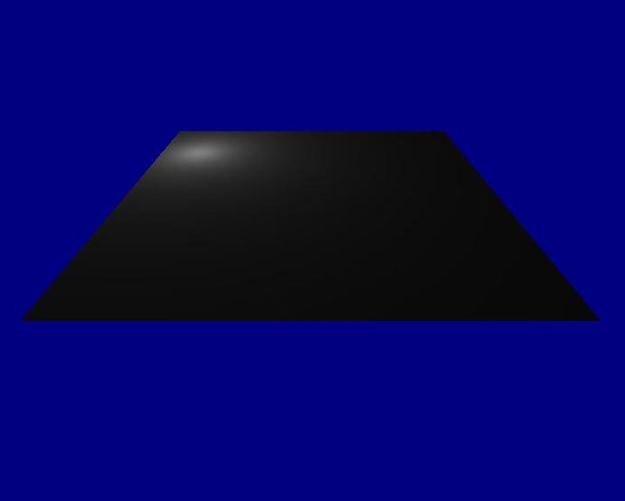
Conclusions
A use of a point light source has been illustrated in this tutorial. The light source shown is basic in nature and there are many additions that can be made to enhance the visual effects.
Dr Henry S Fortuna
University of Abertay Dundee