PS2 Linux Programming
Creating Lighting With Specular Highlights
Introduction
In this tutorial Specular Highlights will be illustrated. The lighting calculations necessary will be computed using vector unit 1.
Background
Shiny surface such as polished metal or glossy paint contain highlight or bright spot. Where the bright spot appears on the material is a function of the position and orientation of the surface, the position of the light source and the position of the viewer. This type of reflectance is therefore view-dependent, so unlike ambient and diffuse terms it’s computation is based on the position of the camera. The fact that this feature is viewer dependent should come as no surprise, since if you stand in front of a mirror and move from side to side, the position of any light source, such as an eclectic light bulb, is also seen to move position in the mirror. An ideal mirror is a pure specular reflector.
At the microscopic level a specular reflecting surface is very smooth, and usually the microscopic surface elements are oriented in the same direction as the surface itself. Specular reflection is merely the mirror reflection of the light source in a surface. In order to model specular reflection we need to understand the physics of reflection.
Reflection is a special case of Snell's laws, which state that:
· The incoming ray, the surface normal, and the reflected ray all lie in a common plane.
· The angle that the reflected ray forms with the surface normal is equal to the angle that the incident ray makes with the surface normal.
This is illustrated in the diagram below:
![]()
Snell's law, however, applies only to ideal reflectors. Real materials other than mirrors and chrome tend to deviate significantly from ideal reflectors and it is convenient at this point to introduce an empirical model that is consistent with observations.
In general it is expected that most of the reflected light will travel in the direction of the ideal ray. However, because of microscopic surface variations some of the light is expected to be reflected just slightly offset from the ideal reflected ray. As we move further away from the position of the ideal reflected ray (in the angular sense) we expect to see less of the reflected light. These features are illustrated in the diagrams below:
One function that approximates this falloff in light intensity is called the Phong Illumination model. This model is purely empirical and has no physical basis, yet it is one of the most commonly used illumination models in computer graphics. Essentially, if the eye is right on the reflection direction, the contribution from the specular component is higher than when the eye direction is farther from the reflection direction. We can also imagine that for a perfect reflector, there will be a quicker fall-off than for a less ideal reflector. We model the speed of that fall-off (and therefore the reflectivity of the surface) with the a shininess factor for the material of the surface. The basis of the calculations are illustrated in the diagram below.
The plots below shows the how the Phong reflectance drops off based on the viewer's angle from the reflected ray for various values of nshiny.
We can compute the cosine term of the Phong specular illumination using the following relationship (just like in the diffuse component, we do not wish to compute the cosine of the angle directly):
The V vector is the unit vector in the direction of the viewer and the vector R is the ideal mirror reflectance direction. The vector R can be computed from the incoming light direction and the surface normal as shown in the diagram below.
Leading to the relationship:
Another approach for computing Phong's illumination uses the following equation (Blinn & Torrance Variation):
In this equation the angle of specular dispersion (N.H) is computed by how far the surface's normal is from a vector bisecting the incoming light direction and the viewing direction.
It is left as an exercise for the reader to consider how this equation and the previous equation differ.
Example Code
In order to perform the lighting calculations the position and colour of the light source and the position of the camera must be passed to VU1 along with the other required data discussed in previous tutorials. This is illustrated in the diagram below:
The format of the static part of the packet sent to the VU is illustrated below.
|
Address |
Data |
|
0 |
Scaling Vector |
|
1 |
Point Light Colour |
|
2 |
Point Light Position |
|
3 |
Camera Position |
|
4 |
Unused |
|
5 |
Unused |
|
6 |
Unused |
|
7 |
Unused |
|
8 |
Transformation Matrix Row #0 |
|
9 |
Transformation Matrix Row #1 |
|
10 |
Transformation Matrix Row #2 |
|
11 |
Transformation Matrix Row #3 |
|
12 |
World Matrix Row #0 |
|
13 |
World Matrix Row #1 |
|
14 |
World Matrix Row #2 |
|
15 |
World Matrix Row #3 |
VU1 Data Memory Layout
Specular lighting calculations are performed using the following VU code which uses the Blinn & Torrance Variation (note that the complete VU code is included with the downloadable source):
lq.xyz Cam, CamPos(vi00)
sub.xyz Cam, Cam, Vert
VectorNormalizeXYZ Cam, Cam
add.xyz HalfVec, Cam, ToLight
VectorNormalizeXYZ HalfVec, HalfVec
VectorDotProduct fSpecIntensity, HalfVec, Norm
mul.x fSpecIntensity, fSpecIntensity, fSpecIntensity ; Square it
mul.x fSpecIntensity, fSpecIntensity, fSpecIntensity ; 4th power
mul.x fSpecIntensity, fSpecIntensity, fSpecIntensity ; 8th power
mul.x fSpecIntensity, fSpecIntensity, fSpecIntensity ; 16th power
mul.x fSpecIntensity, fSpecIntensity, fSpecIntensity ; 32nd power
add.x fIntensity, fIntensity, fSpecIntensity ; Get the total intensity
max.x fIntensity, fIntensity, vf00 ; Clamp to > 0
mini.x fIntensity, fIntensity, vf00[w] ; Clamp to < 1
lq fLightCol, LightCol(vi00) ; Load the light colour
mul.xyz fLightCol, fLightCol, fIntensity[x] ; Scale the colour by the intensity
loi 128
mul fLightCol, fLightCol, i ; Scale from 0-1 to range 0-127
ftoi0 iLightCol, fLightCol ; Convert to ints
sq iLightCol, NormStartOut(Counter) ; And write to the output buffer
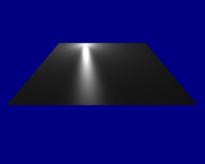
In the example application, a flat terrain (with all the vertex normals pointing upwards at right angles to the terrain) is lit by a single point light source with a position that circles round above the terrain. The lighting effect is illustrated in the diagram shown below.
Conclusions
The calculation of specular highlights using a point light source has been illustrated in this tutorial. There are many variations which are possible and it is left up to the reader to experiment with these lighting models.
Dr Henry S Fortuna
University of Abertay Dundee