PS2 Linux Programming
Viewing in Three Dimensions
Introduction
This tutorial will describe the background and main techniques necessary to configure the matrices required for the viewing of objects in three dimensions using the Perspective Transformation.
To compute the view of a 3D model, the 3D world coordinates of the vertices in the model must be converted to 2D screen coordinates, which determine which screen pixel represent each vertex. This conversion depends on the position and orientation of the virtual camera in the 3D space and on the type of projection desired.
These notes will describe the steps required in order to convert camera coordinates into corresponding screen coordinates. During this conversion process, clipping of objects to the view frustum will also be described.
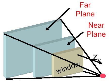
Figure 1 below shows the basic configuration for a perspective viewing transformations.
Figure 1
First there is a viewing window or screen onto which the 3D objects are projected. In order to limit the size of the potentially infinite viewing volume two additional planes are introduced, the near plane and the far plane. Only objects in the volume bounded by the near and far planes and the other four sides of the view frustum will be projected onto the screen. Objects outside the view frustum will be rejected.
The viewing volume must be defined relative to the coordinate system (or axes) of the camera and this is illustrated in figure 2 below.
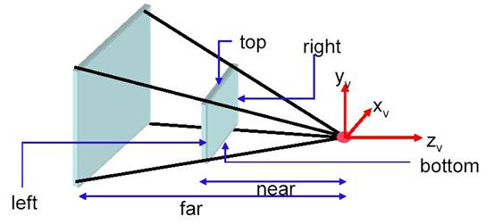
In Figure 2 the viewer or camera looks directly along the negative z axis, the y axis points upwards and the x axis points to the right. The z axis passes straight through the centre of the viewing volume and the near and far planes.
A perspective projection viewing volume is defined in Figure 3.
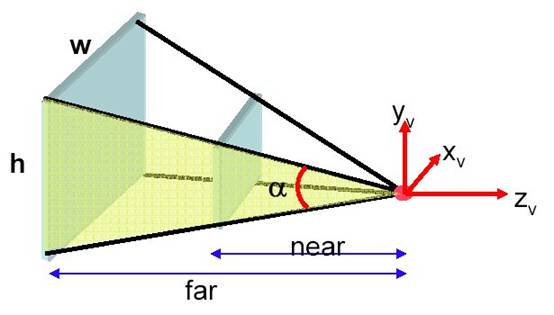
The near plane is situated n units from the camera and the far plane f units from the camera. The viewing angle or field of view (FOV) is defined as the angle alpha, which is an angle defined in the direction of the y axis. The aspect ratio of the view frustum is defined as A = w/h.
In order to determine which objects are seen in the viewing window, it is necessary to clip objects against the six planes that form the view volume. Clipping against arbitrary 3D planes requires considerable computation which in general can and should be avoided. For fast clipping (which is supported by the hardware of the PS2), the viewing volume can be transformed into a canonical viewing volume which is illustrated in Figure 4.
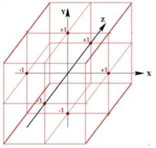
Figure 4
This volume is a cube with side dimensions of 2 units. The cube extends between –1 and +1 in all of the three axes. Using the canonical viewing volume it is a much simple matter to determine which objects should be drawn or clipped out of the scene. Objects will only be drawn if their vertices meet the following criteria: (–1 £ x £ 1); (–1 £ y £ 1); (–1 £ z £ 1). In general, the situation is more complex than this and polygons or lines located partly inside and partly outside this volume will need to be modified in a way such that only the part inside the canonical view volume is kept. Such algorithms however are beyond the scope of this present tutorial. Polygons that lie completely outside the canonical view volume do not need further treatment and will be invisible to the viewer – they will be rejected from the remainder of the drawing pipeline. Polygons that lie completely inside the canonical view volume can be drawn without requiring further investigation.
A 4x4 transformation matrix for homogeneous coordinates is required which will map the truncated pyramid viewing frustum described earlier into a standard cube in homogeneous coordinates such that: (–1 £ x/w £ 1); (–1 £ y/w £ 1); (–1 £ z/w £ 1). First, the case will be considered of a symmetrical perspective projection with a field of view of 90 degrees and a square window with an aspect ration of unity. The centre of projection is at the origin and the viewing window (screen) is located at z = -1 as illustrated in figure 5.
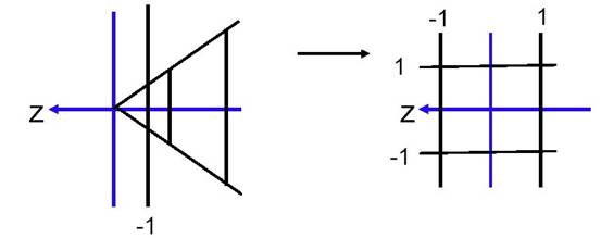
Figure 5
Consider the following transformation:
Figure 6
The resulting points have affine coordinates (x/-z, y/-z, -1) which is precisely the intersection of the line from the origin to the point (x, y, z) with the plane z = -1. This transformation is sufficient if there is no interest in the z coordinate since after division by w’ = -z the result z = -1 is always obtained for the z coordinate. Thus, due to the perspective division it is no longer possible to determine the z value which is required for hidden surface removal in the z-buffer.
However, it is still possible to construct a projection matrix such that z is a monotonically increasing (non-linear) function of the depth (-z) of the point in the range –1 to +1 which can be used for visible surface determination and removal.
z’ is determined by the coefficients in the third colum of the transformation matrix given in figure 6. A new transformation matrix can be specified as shown in figure 7 which will have two additional parameters (a and b) which will transform the z coordinate. Note that there is no need for z’ to depend on x or y so the first two coefficients of the third row are zero.
Figure 7
Using the transformation in figure 7, the z coordinate of an arbitrary point (x, y, z, 1) in camera coordinates is transformed to the point:
It is required that the near clipping plane (n) is mapped to 1 and the far clipping plane (f) is mapped to –1 which leads to the two equations given below, which has two unknowns a and b.


Solving these equation for a and b provides:


Giving the following transformation matrix:
Figure 8
The z coordinate in the canonical volume which results from the transformation given in figure 8 varies non-linearly with increasing values of –z. This characteristic of the z buffer is illustrated in figure 9 which shows the z buffer fill characteristics for near plane values of 0.1, 1 and 10 and a far plane value of 100.

Figure 9
It can be seen from figure 9 that changes in the z position of a point close to the near plane result in large changes in the transformed z coordinate, whilst changes in the z position of a point far from the near plane result in only small changes in the transformed z coordinate. Also, the closer the near plane is to the eye point the less uniformly the z-buffer is filled. In practice, care must be taken in positioning the near clipping plane: better z buffer performance can be obtained if the near plane in placed as far as possible from the eye point, but this can cause visual problems for the rendered scene. A compromise must be reached fro the positioning of the near clipping plane which will depend on a number of things including the visual effect required, the type of scene being rendered, etc.
The vertical viewing angle alpha, as seen in figure 3 is also known as the Field of View (FOV). It is convenient to specify the frustum by the vertical viewing angle (FOV) and the aspect ratio A = w/h. Both of these parameters, FOV and A are independent of z. Now a symmetrical perspective projection with a FOV not equal to 90 degrees and an non unity aspect ratio can be reduced to the case discussed above by scaling x and y by the scaling matrix:

The complete projection matrix is now:
Figure 10
After points are transformed with the perspective transformation matrix given in figure 10 it is then possible to perform clipping to reject points outside the view frustum from further processing. For trivial clipping, any points which do not satisfy all of the following conditions can be clipped and require no further processing:
(–1 £ x’/w’ £ 1); (–1 £ y’/w’ £ 1); (–1 £ z’/w’ £ 1).
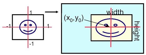
Figure 11
As discussed above, the projection transformation matrix given in figure 10 transforms points onto a screen with dimensions of 2 units by 2 units as shown at the left hand side of figure 11. It is required that the screen be mapped to a real screen with dimensions width and height and offset (Xo, Yo) as illustrated. Also, it is necessary to expand the transformed z coordinate to make use of the full range of the z buffer. In the PS2 configuration being used, there is a 24 bit z buffer which ranges from 0 to 16,777,215 (Zrange) with 0 being furthest away from the eye. Transforming from the canonical view to the required view port can be accomplished with the following transformation matrix.

This transformation will provide the correct screen coordinates and z buffer value.
This tutorial has illustrated the use of the perspective transformation to provide viewing of objects in three dimensions. The z buffer value has been obtained to provide hidden surface removal and a canonical transformation has been used to facilitate frustum clipping.
Dr Henry S Fortuna
University of Abertay Dundee